|
...::::: NOVELTIES
:::::.....
|

PМ-303
PTA system for automated surfacing with CNC control

PM-WMO-120
Welding mechanical oscillator

PM-RM-100
Rotator-Manipulator

PP-7
Compact plasma torch for outer surfacing of small-sized parts

PM-PF-10
Powder feeder
|
|
...::::: EVENTS
:::::.....
|
|

|
|
...::::: ADVERTISING
:::::.....
|
|
 |
| 1 · · · 2
· · · 3 · · · 4
· · · 5 · · · |
|
|

|
| New plasma torches
for PTA-surfacing |
|
Article: Author - Som А.I.
Process of Plasma Transferred Arc (PTA) surfacing
is noted for unique technological capabilities [1,
2]. Small depth of penetration in the basic metal,
high precision, high production standards and an ability
of surfacing of the various alloys - all that makes
it irreplaceable at surfacing of valves, stop valves,
extruder and heat softening device, tools and many
other parts. At the same time there are many parts
for which PTA-surfacing is not applied because of
different reasons - in many cases because of lack
of reliable high-efficiency and various design plasma
torches.
The Plasma-Master Co., Ltd. develops the collection
of plasma torches for the various purposes. That allows
to fill specified lack very largely. At that the world
experience and results of own researches of the author
are used widely. The special attention is given for
choice of the rational scheme of feeding of additive
powder in an arc, search of optimum ratio of geometrical
parameters of distributive unit and nozzle part of
plasma torch, and also quality of protection of a
welding pool.
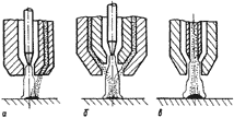
The scheme of powder feeding in arc. It is
distinguished the plasma torches with internal and
external scheme of feeding of an additive powder in
an arc. In the first case the powder comes through
arc from outside of plasma torch by one or several
lateral channels (fig. 1, a), and in the second -
inside of it as the distributed stream through a narrow
ring slit between plasma forming and focusing nozzles
(fig. 1, b).
|

Fig. 1. Schemes of feeding of additive powder in arc:
a - external; b - internal; c - through sleeve cathode |
One more scheme of feeding of powder in arc is possible
- axially through the sleeve cathode (fig. 1, c).
The experiments executed by experts of Plasma-Master
Co., ltd. and described in work [3], testify to its
availability, especially in the field of high productivities
(> 8 kg/h). However because of the technical complexity
plasma torches with such scheme have not found practical
application yet, therefore they are not considered.
|
|
Plasma torches with external feeding of powder are
enough widely applied abroad, they are simpler and
are considered as more reliable from the point of
view of a contamination of channels and nozzles by
sparks of liquid metal, however they yield essentially
to plasma torches with internal feeding in efficiency
of heating and fusion of powder [4] as the powder
is much less time in an arc. In such plasma torches
losses of powder and power inputs are much higher.
Especially it is shown under surfacing with the high
productivity (> 3 kg/h). Besides one-way lateral
feeding of powder results in deformation of arc and
hence in trouble of surfacing stability and in deterioration
of formation of deposited bead. Therefore in the development
we have preferred the internal scheme as more effective.
|

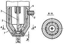
Fig.2. Unit of distribution and powder feeding in arc:
1 - focusing nozzle; 2 - stabilizing nozzle; 3 - electrode;
4 - ring distributing chamber; 5 - input nipple |
All plasma torches of Plasma-Master Co., Ltd. independently
of their design contain typical distributive unit
(fig. 2), consisting of the ring chamber and evenly
located on a circle of longitudinal grooves along
which the powder is blown into an arc on the appointed
angle. The sizes, quantity and inclination of grooves
are selected in such a way that powder particles get
into the most high-temperature area of arc at the
output from focusing nozzle.
|
|
The coefficient of powder distribution uniformity
on a circle at the optimum transport gas flow is provided
not below 0,8, and flight speed of particles at the
moment of input in arc - no more 1,5...2,0 m/sec.
Thermal and power characteristics of plasma torches.
The basic parameters of effective work of torch
is its thermal and power characteristics. As they
essentially depend on a torch design and parameters
of its work, it is necessary to find such typical
solution of a units design that would reduce thermal
losses to a minimum. Especially it concerns of focusing
nozzle, being an additional element in plasma torches
with internal powder feeding.
Thermal characteristics of plasma arc are investigated
by the method of flow calorimetry on model plasma
torch in which cooling of each unit was independent.
Efficiency of part heating estimated by the thermal
stream that is perceived by face of the water-cooled
anode. The water flow through the anode and torch
units was measured by rotameter, the current and the
arc voltage - accordingly by ammeter and voltmeter
of a class 0,2. The difference of values of water
temperature dТ at the input and the
output from plasma torch was defined by special thermobatteries
consisting of five chromel-copel thermocouples and
was registered by multipoint potentiometer KSP-4.
The meter-temperature circuit was calibrated by reference
mercurial thermometers with scale factor 0,1°C. Use
of thermobatteries has allowed to receive without
the additional amplifier an initial signal, sufficient
for registration and processing. The relative error
of measurement dТ of water did not exceed
3 %.
Measurements were carried out with the following
combinations of diameters of stabilizing and focusing
nozzles (Ds/Df): 2/4; 3/6; 4,0/7,5 and
5/9 mm. Lengths of each channel of stabilizing nozzle
were equaled to its diameter, and focusing - 0,2 Df.
The deepening of a tungstic electrode in stabilizing
nozzle was 0,8 Ds, distance from the
end face of torch up to the anode - 8 mm. Some results
of researches are submitted on fig. 3, 4.
|
|

Fig. 3. Influence of arc current
on the thermal capacity spent for heating of part
Qp, cathode Qc, stabilizing Qs and focusing Qf nozzles
(a) and accordingly on factors of distribution of
thermal capacity, Hp, Нc, Hs and Hf (b) (Ds/Df=4,0/7,5
mm; Qpl=2 l/mines; Qtr=5 l/mines; Q - total thermal
capacity of arc; Hp - efficiency of heating)
|
Influence of arc current on effective thermal capacity
Qp and efficiency of part heating
Hp for plasma torch with nozzles 4,0/7,5
mm at typical flows of plasma Qpl and
transport Qtr gases is shown In Fig.
3 as an example.
Apparently, Hp is rather high, in an
interval of currents 50…250 A it makes 80...60 % that
is close to efficiency of plasma torches that are
used for welding and cutting [5, 6]. Presence of additional
small length focusing nozzle practically doesn't tell
on effective efficiency of part heating. With rise
of arc currents fixed reduction Hp is
bound up with growth of losses in nozzles as a result
of increase of diameter of arc [7].
The plasma and transport gas flow influences on effective
thermal capacity and efficiency of arc in different
ways.
|
|
So, when plasma gas flow increases (fig. 4, a) then
parameters Qp and Hp grow
a little, reaching maximum at Qpl=5...6
l/min, that is explained by increase of energy concentration
in arc owing to its greater squeezing, reduction of
losses in stabilizing nozzle and intensification of
convective heat transfer of plasma with the anode.
However in practice it is impossible to use this effect,
as it is necessary to limit plasma gas flow because
of excessive penetration of the basic metal.
|

Fig 4. Dependence Hp, Qp, Qc, Qs, Qf on Qpl (a) and
Qtr (b) gases (Ds/Df=4,0/7,5 mm; Ia=150 A): a - Qtr=5;
b - Qpl=2 l/min |

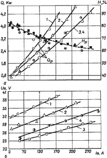
Fig 5. Dependence Hp, Qp (a) and voltage Ua
(b) on arc current Ia: 1 - Ds/Df=2/4; 2 - 3/6; 3 -
4,0/7,5; 4 - 5/9 mm
|
|
When transport gas flow increases, on the contrary,
reduction of effective thermal capacity and efficiency
of arc (fig. 4, b) occurs. It is caused by that transport
gas has not a compressing effect on arc because of
big diameter of focusing nozzle, and only gas bleeds
heat of arc. However, as this influence is little
then when you select the gas flow, first of all, it
is necessary to start with conditions of the best
distribution of a powder in plasma torch.
Effective means of increase of thermal capacity of
arc on other equal conditions is reduction of diameter
of plasma torch nozzles, i.e. increase of its compression
ratio.
As results of calorimetry show (fig. 5, a), reduction
Ds/Df from 4,0/7,5 or 5/9 up to 2/4
mm raises values Qp more than 1,5 times
for the present design of plasma torch. It is necessary
to note, that value of effective efficiency of arc
practically does not change at the same time; the
increase of heat-embedding into the anode is the result
of voltage rise in arc (fig 5, b), i.e. as a result
of increase of consumed power from source. With reduction
of diameter of nozzles energy concentration grows
in arc also: the factor of concentration measured
by method in work [8] is increased accordingly from
2,0... 2,5 up to 6,0... 6,5 1/sm*sm. This factor is
very important during surfacing of small-sized parts
as it allows to adjust character of transfer of heat
into part rather subtly. However to reduce diameter
of nozzles it is possible only up to the certain limit
caused by stability of burning of arc [9, 10].
For each combination Ds/Df of nozzles
there is a certain range of currents, in which the
arc (in the presence of additive powder) burns steadily,
i.e. double arc-formation is absent, and dynamic arc
head does not prevent from good formation of deposited
bead. It is established experimentally, that for Ds/Df
=2/4 mm these values are 20...110 A; for 3/6 mm -
20...170 A; 4,0/7,5 mm - 30...220 A; for 5/9 - 40...300
A. The choice of this or that combination of nozzles
in each concrete case is dictated by technological
reasons (necessary heat-embedding into a part, character
of heat distribution over a surface, productivity
of surfacing etc.).
Technical data
of new plasma torches
A variety of designs and versions allows to cover
a wide spectrum of parts and materials for surfacing.
Ni-, Co-, Fe- and Cu-base alloys may be successfully
cladded both on external, and internal surfaces of
parts, including hard-to-reach places (plasma
torch PP-21).
Distinctive feature of configuration of considered
plasma torches, except for PP-6-01
and PP-6-02,
is a horizontal arrangement of holders that allows
to take out communications from a working zone and
to make them universal both when deposition of external
and internal surfaces. The connection unit of plasma
torches allows to install and remove them for service
quickly and also to make replacement of one type of
torch to another.
The basic technical data and field of application
of plasma torches are given below in the table.
Apparently, by the basic parameters, in particular
by productivity and efficiency, they surpass well-known
analogues notably. Especially plasma torch PP-6-01
is worthy of notice that provides for the greatest
productivity of deposition (up to 10 kg) under current
is no more than 400 A. Hereto it is necessary to add
high quality of protection of the welding pool, achievable
due to an original design of gas lens. It allows successfully
to carry out broad-zoned surfacing of oxidation-sensitive
Fe-base high alloys and steels.
|
|
List of used literature
1. Гладкий П.В. Исследование и разработка
технологии плазменно-порошковой наплавки. Дис... канд.техн.наук.
- Киев, 1972, - 232 с.
2. Гладкий П.В., Фрумин И.И. Плазменная наплавка
// Автоматическая сварка.- 1965.- №3.- С.23-27.
3. Dilthey U., Kabatnik I. Zentrale pulvorzufuhr
beim Plasma-Pulverauftragschweiben // schweissen &
schneiden.- 1988.- №12.- S.766-771.
4. Гладкий П.В., Павленко А.В., Зельниченко А.Т.
Математическое моделирование на-грева порошка в дуге
при плазменной наплавке // Автоматическая сварка.-
1989.- №11.- С.17-21.
5. Стихин В.А., Пацкевич И.Р. Определение
тепловых характеристик сжатой дуги // Сварочное производство.-
1967.- №9.- С.26-27.
6. Эсибян Э.М. Плазменно-дуговая аппаратура.-
Киев: Техника, 1971.- 162 с.
7. Губенко В.А., Молоканова Т.В., Новиков А.М.
Влияние тока сжатой дуги и расхода газа на нагрев
сопла // Автоматическая сварка.- 1975.- №5.- С.45-47.
8. Демянцевич В.П., Михайлов Н.П. Исследование
распределения тепла микроплазменной дуги при смещении
центра пятна нагрева с оси стыка // Сварочное производ-ство.-
1973.- №6.- С.1-3.
9. Байнбойм Д.И., Ратманова Ж.В. Энергетические
характеристики дуги, горящей в аргоне, с различной
степенью сжатия // Сварочное производство.- 1974.-
№5.- С.1-3.
10. Кудинов В.В., Кулакин И.Д. Об устойчивости
сжатого дугового разряда в канале электропроводного
сопла // Автоматическая сварка.- 1964.- №6.- С.33-38.
|

1 · · · 2
· · · 3 · · · 4
· · · 5 · · ·
|
|